WHAT'S ANTI ROLL BAR ?
An anti-roll bar (roll bar, anti-sway bar, sway bar, stabilizer bar) is a part of many automobile suspensions that helps reduce the body roll of a vehicle during fast cornering or over road irregularities. It connects opposite (left/right) wheels together through short lever arms linked by a torsion spring. A sway bar increases the suspension's roll stiffness—its resistance to roll in turns, independent of its spring rate in the vertical direction. The first stabilizer bar patent was awarded to Canadian inventor Stephen Coleman of Fredericton, New Brunswick on April 22, 1919.[1][2] Anti-roll bars were unusual on pre-war cars due to the generally much stiffer suspension and acceptance of body roll. From the 1950s on, however, production cars were more commonly fitted with anti-roll bars, especially those vehicles with softer coil spring suspension.
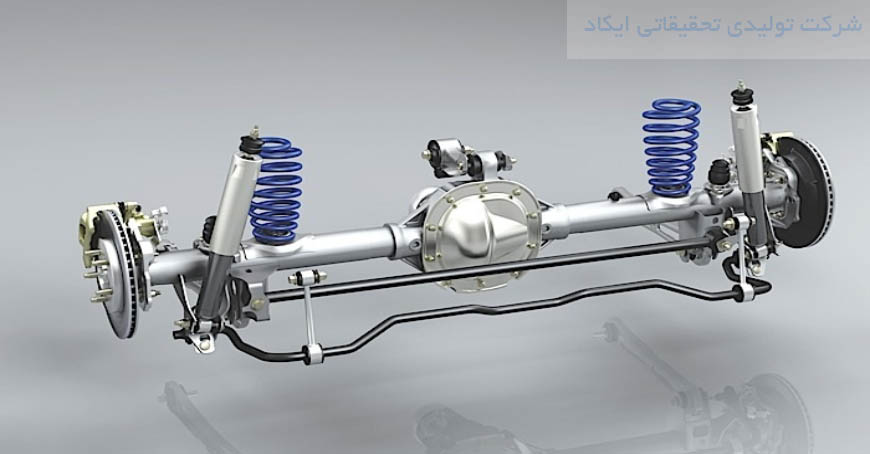
An anti-sway or anti-roll bar is intended to force each side of the vehicle to lower, or rise, to similar heights, to reduce the sideways tilting (roll) of the vehicle on curves, sharp corners or large bumps, essentially counteracting the centrifugal forces of the vehicle rounding the curve. With the bar removed, a vehicle's wheels can tilt away by much larger distances (as shown by the SUV image at right). Although there are many variations in design, a common function is to force the opposite wheel's shock absorber, spring or suspension rod to lower, or rise, to a similar level as the other wheel. In a fast turn, a vehicle tends to drop closer onto the outer wheels, and the sway bar soon forces the opposite wheel to also get closer to the vehicle. As a result, the vehicle tends to "hug" the road closer in a fast turn, where all wheels are closer to the body. After the fast turn, then the downward pressure is reduced, and the paired wheels can return to their normal height against the vehicle, kept at similar levels by the connecting sway bar. One way of estimating antiroll bar stiffness: T=Vehicle track width (inches) K=Fractional lever arm ration (movement at roll bar / movement at wheel) d=Bar diameter (inches) R=Effective arm length (inches) L=Half length of bar (inches) S=Length of lever arm (inches) Q=Stiffness (lb*in per degree) [3] Because each pair of wheels is cross-connected by a bar, the combined operation causes all wheels to generally offset the separate tilting of the others and the vehicle tends to remain level against the general slope of the terrain.


